The goal of automation is to build an effective monitoring and control system for all components of the engineering infrastructure in the following areas:
Energy Saving
Heating
Lighting
Water Supply
Technological Process
Access Control
Diagnostics and Accident Prevention
Energy Saving
Lighting
Technological Process
Heating
Water Supply
Access Control
Diagnostics and Accident Prevention
SMARTEH EQUIPMENT
Main Control Unit
The main controller unit LPC-2.MC8 with Ethernet Modbus network interface is the primary intelligent element in the installed system. It is an open programmable (IEC 61131-3) controller where the application program runs separately for each room.
The main control unit is used for communication with other controllers and the host computer. The device is powered by a 230V AC supply. Input and output devices (switches, lights, valves) and communication modules, such as the room temperature panel and the access control module, connect directly to the controller bus.

Internal Reader with Pocket and Commands
The internal electronic key pocket (LPC-2.CH1) is designed for access control, card insertion, and guest request transmission.
Upon entering the room, the key card must be inserted into the reader pocket. If the card is detected, the lighting turns on, the flood control system and water supply shut-off valve are activated, and the heating is set to comfort mode.
“Do Not Disturb” or “Room Service” signals can be activated using the command buttons. When leaving the room, the key card must be removed from the pocket.
The room returns to idle mode; after a short delay, the lighting, flood control system, and water shut-off valve are turned off, while heating and other room systems switch to energy-saving mode.

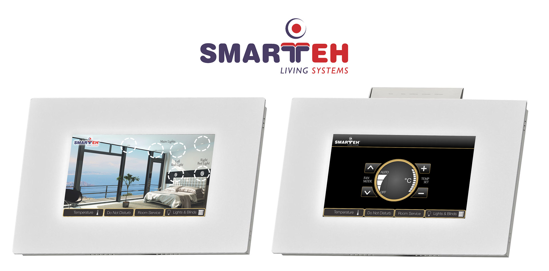
Climate Control Panel
The room temperature regulator (LPC-2.DP1) is designed to adjust the temperature in the room. The device features a temperature sensor, light sensor, and four buttons. “Up” and “Down” buttons control temperature and fan speed selection. A bar graph displays the current status.
Using the up and down buttons, the desired room temperature can be selected; the setting is indicated by a light position and shown on the display. Maximum and minimum temperature limits can be adjusted over the network.
It is also possible to enable or disable the display of the actual temperature, time, or operating mode. Ventilation can be adjusted to constant speeds I, II, III, set to automatic (AUTO), or turned OFF. Ventilation status is shown by a light position on the display. The light sensor manages the display intensity so that the brightness does not disturb the guest during rest.
Integration with External Systems
SMARTEH equipment is the lower hardware execution level of the system, which can operate independently, but this is not enough for full functionality.
That is why SMARTEH provides the possibility of integration with other systems.
A full-featured complex consists of the following components:
- Hotel Management System (HMS) or Technological Process Management System (TMS)
- Access Control System (guest and staff)
- Building Management System (BMS)
- Dispatching System
Application in Hotels
The hotel system exchanges data with the dispatching system regarding room status, guest presence, minibar usage, active electrical appliances, and climate. It also transmits commands to the dispatching system for minibar access, returning a room to occupied mode after idle, or switching it back to idle mode.
- Through the software integration interface, the hotel system connects to the Smarteh Interface Service module via the TCP/IP protocol.
- Smarteh Interface Service exchanges data via SQLServer with the Building Management System (Smarteh BMS or any other).
- The Building Management System controls the room controllers via TCP/IP, monitors their status, collects sensor readings, and provides a visual display of all devices in the rooms.

Building Management System (BMS)
The main task of the Building Management System (BMS) is to display the status of all engineering systems and manage them.
BMS interacts with hardware devices and receives all the information necessary for operation from them.
The visualization is built on a hierarchical principle. Each plan can be detailed to the required level: complex, building, floor, room, device.
Furthermore, the system processes events and automatically responds to typical cases or notifies the operator about unusual or emergency situations.
other products